Eris 2010 8-Bit Computer
Eris 2010 is homebrew 8-bit computer in the style of the microcomputers of the 1970/80s. Here you find a little description of the project including some screenshots and a video, as well as the complete source code for the soft- and hardware.
- Overview ⟸ General information. Continue reading.
- User Manual ⟸ Got an Eris 2010? Get it running!
- Developer Documentation ⟸ The gory details.
- Repository (Clone) ⟸ Eris 2010 source code. It’s free!
Overview
Hardware
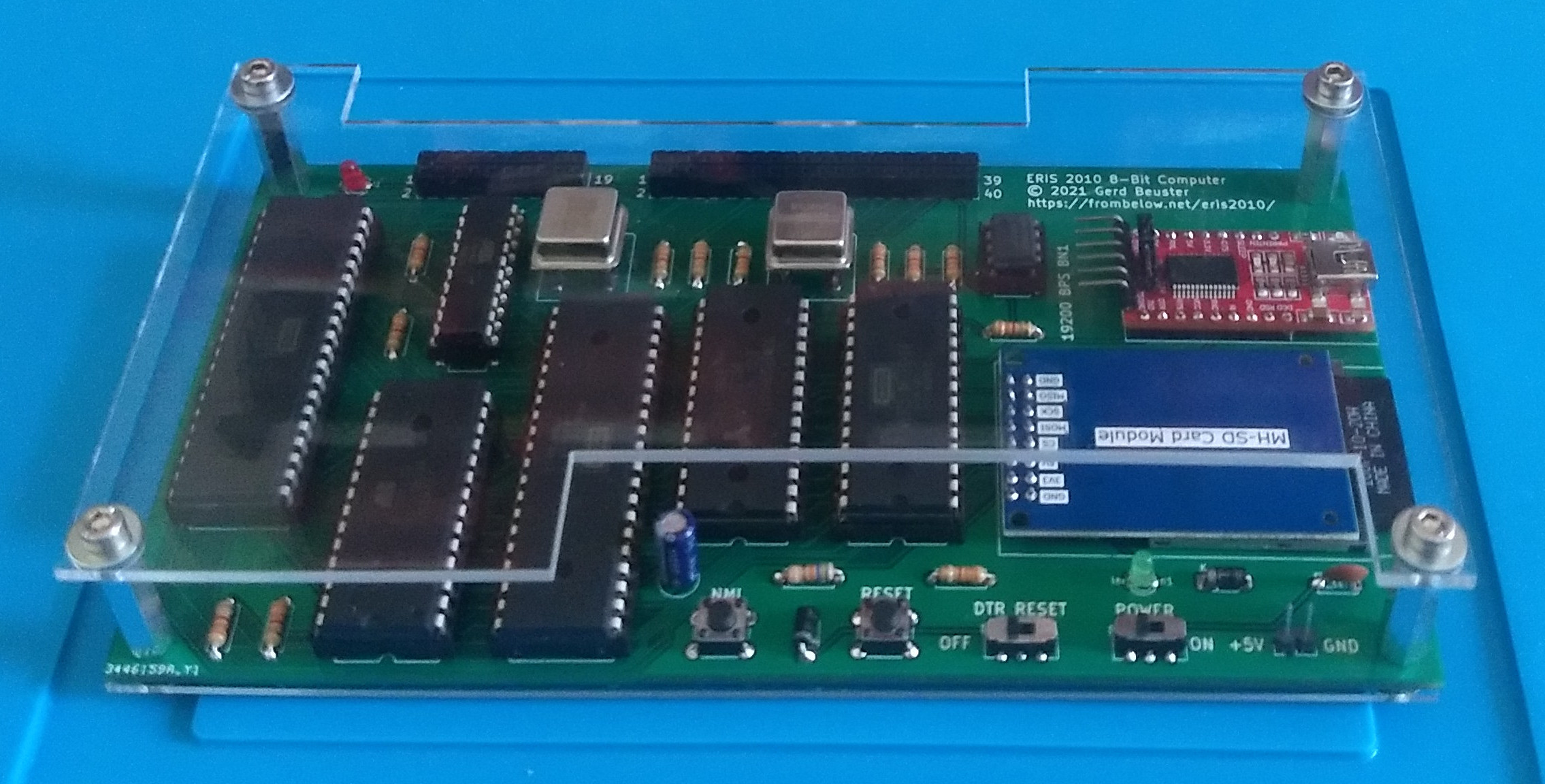
Eris 2010 is homebrew 8-Bit computer in the style of the microcomputers of the 1970/80s. It is build around the WDC 65C02 MPU. This is a slightly updated version of the legendary MOS 6502 used for example in the Commodore VIC20 and the Apple I and ][. The other main components are 32 KB RAM and 8 KB EEPROM. While the old home computers from the 1970/80s came with a keyboard and connected to a TV or monitor, this design provides a serial communication interface. Therefore it is more similar to modern microcontrollers or very early home computers like the Altair 8800 than to later computers of the home computer era like the Commodore 64 or the Apple ][. The serial interface is provided by a 6551 ACAI. This chip has been used in computers from the era like the Commodore PET and the Commodore Plus/4 to connect a modem. In the Eris 2010, the 6551 ACAI connects to a (modern) USB2Serial adapter. This allows to use a standard laptop or desktop computer as a terminal for the 8-bit machine.
The second auxiliary chip is a 6522 VIA. Among other things, this chip provides a bunch of GPIO lines. A few of them are used to connect an SD card reader, providing a mass storage device to Eris 2010. The remaining lines are freely programmable I/O ports. SD cards are written in a very simple, homebrew data format. When the computer is powered, the “operating system” in EEPROM presents a list of the programs on the SD card and acts as a bootloader. Alternatively, programs can be uploaded via the serial interface.
The bus is orchestrated by an ATF16V8 EEPLD. While the first chips with programmable logic were developed in the 1970/80s, most computers of the era did not use programmable logic, but discrete logic chips. Using an EEPLD allows to keep the chip count low, and I wanted to play with programmable logic a bit.

Reset logic is based on the good old 555 chip. We find similar circuits in home computers as well.
The first version of the computer was build on a breadboard. Once the breadboard design was functionally complete and stable at 4 Mhz, the design was fixed on a PCB in through-hole technology. In order to allow connection of additional peripheral devices and extensions, two interfaces were added: A user port to provide access to the free I/O ports, and an expansion port exposing the buses and other internal lines. The KiCad design files of the PCB are included in the repository.
Here is a little video of Eris 2010 in action.
Software

Eris 2010 can be programmed in assembler, C, and Forth. Directory
sw/ contains the games Snake and Tic-Tac-Toe (no fan of WarGames
should go without one), the famous 10 PRINT program (check out this
book on the cultural significance of
10 PRINT if you do not know it already), and some test programs. The
contrib/ directory contains additional third party software ported
to Eris 2010. Most notably, it contains a port of Tali Forth 2, a
very capable Forth system for 65C02 MPUs. Other software includes
Wozmon, Steve Wozniak’s “operating system” for the Apple I,
Microchess, the first commercial game for microcomputers, some other
games, and a port of Eliza. The contrib directory also contains a port
of Tiny BASIC, so you can even program the system in BASIC, just like
in the old days.
All components of the system (except for the third party software in
contrib/) are free soft- and hardware. You can find all source code
in the repository linked at the top of this page.
User Manual

So you are one of the lucky few who got a pre-assembled Eris 2010 computer including an SD card with some software!
Getting started
Insert the SD card that comes with your Eris 2010 into the SD card reader. The standard way to communication with this 8 bit computer is via the USB2Serial adapter. For this connect your Eris 2010 via a Mini USB cable to your computer. On your desktop or laptop computer, you need a terminal program.
Linux
Run a terminal program like tio. tio should be available in the
package store of your distribution. If not try minicom or
picocom. The interface is probably available as
/dev/ttyUSB0. Connect to Eris 2010 by
tio -b 19200 /dev/ttyUSB0
Press a key or the reset button on Eris 2010. If this does not work,
try the command above with /dev/ttyUSB1, /dev/ttyUSB2, …
Windows
When you connect Eris 2010 to your desktop or laptop computer, you first have to install the device driver for the USB2Serial connector. You can download it from the manufacturer. Now connect Eris2010 to a USB port. Next, you have install a terminal program. For Windows users, a common terminal program is PuTTY. After installation, there is a folder PuTTY in your start menu. From this folder, choose PuTTY.
When putty starts, click the radio button “Serial”. Set “Serial line” to “COM3”, and “Speed” to “19200”. Click “Open”. In the terminal windows, type any character or push the reset button on Eris 2010. You should now be connected to the computer. If this does not work, try “COM1”, “COM2”, … for “Serial Line”.
The default font of PuTTY does not support the Unicode characters used by the 10 PRINT program. I order to run this program, choose “Window/Appearance” and change the font to e.g. @NSimSun.
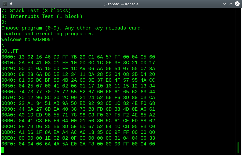
Running programs

You should now see a choice of programs. Typing a number starts the corresponding program. The more interesting programs are:
Tic-Tac-Toe
This should be self explanatory.
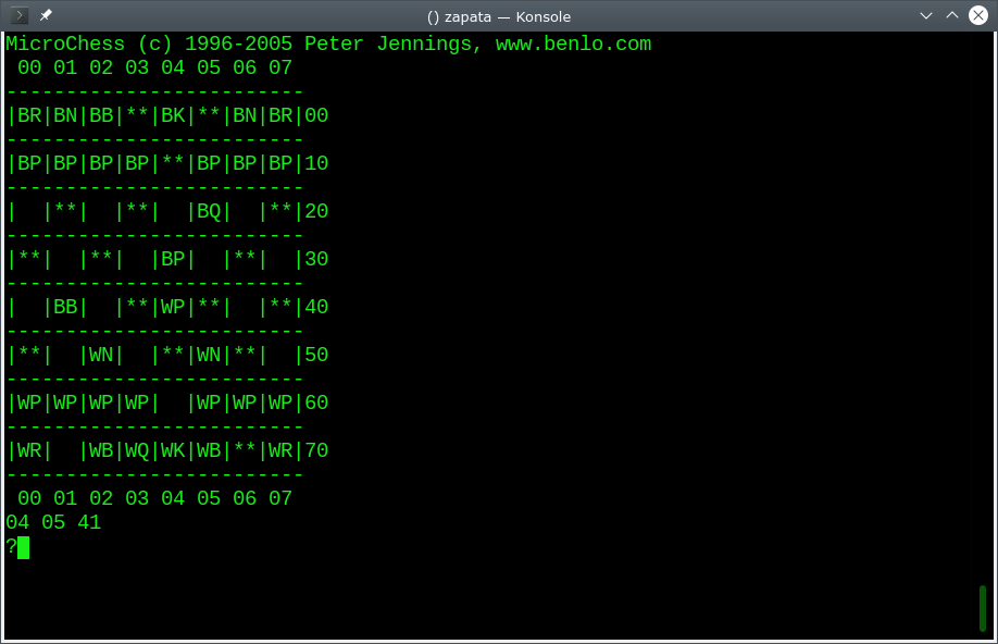
Microchess
Press ‘c’ to set up a new board. Enter moves by giving the field numbers followed by enter, e.g. ‘6444’. Push ‘p’ for the next move of the computer. You can switch the board with ’e’. ‘q’ quits the game.
Microchess is third party software.
TINY BASIC
All input must be in caps!
Tiny BASIC is third party software.
Abandoned Farmhouse
A small text adventure game.
Eliza
A version of Weizenbaum’s famous ELIZA. This version diverges quite a bit from Weizenbaum’s original program, which was more advanced.
Mastermind
A version of Mastermind. There are some divergences from the original rules: When you a number appears once in the code but the player guesses it multiple times,"+" will be output for every wrong spot of the number.
Wumpus
Hunt the Wumpus, a classical computer game: https://en.wikipedia.org/wiki/Hunt_the_Wumpus.
Developer Documentation
Repository Directory Structure
case/- Minimal case consisting of top and bottom plates for laser cutting.contrib/- Third party software. Seecontrib/README.mdfor a description.hw/- Hardware descriptiontools/- PC programs to upload programs and write SD cardroms/- ROM images. Seeroms/README.mdfor a description.sw/- “Userland” software to be loaded into RAM by a suitable ROM. Eris2010 can be programmed in assembler and C.
Main Components

The computer is based on a 65C02 running at 4 Mhz with 32K RAM (AS6C62256-70PCN) and 8 K EEPROM (AT28C64B-15PU). A W65C51N ACAI provides a serial communication interface. A VIA 65C22 provides a GPIO interface. Four of the lines connect an SD card reader via SPI. Bus logic is provided by a ATF16V8B EEPLD. The reset logic is based on a NE555 in a monostable configuration with a little help (an inverter on the AFT16V8B).
The hardware design is rather straightforward; see
hw/pcb/eris2010/eris210.sch for schematics (this is a KiCad file). The
bus logic is documented in hw/bus_logic/bus_logic.pld. The only tricky
part was getting RAM access synced with the CPU clock.
Memory Map

Lowest 32K are RAM, highest 8K are ROM. Up to 4 I/O devices (ACAI or
VIA) can be accessed at addresses below the ROM. One ACAI and one VIA
are required to operate the computer, because they provide a serial
interface (ACIA) and an interface to the SD card reader (VIA). Two
more devices can be connected via the Extension Port. The third I/O
device is active when io_select5 is high and io_select4 low. The
fourth I/O device is active when io_select5 is low and io_select4 is
high. See hw/bus_logic/BUS_LOGIC.PLD for details.
| Area | Content | Location |
|---|---|---|
| ROM | OS | $E000 - $FFFF |
| IO | EXP2 | $D800 - $DFFF |
| EXP1 | $D000 - $D7FF | |
| VIA | $C800 - $CFFF | |
| ACIA | $C000 - $C7FF | |
| RAM | IRQ Vector | $7FFE - $7FFF |
| Heap | … - $7FFD | |
| … | … | |
| Data Stack | … | |
| Program | $0200 - … | |
| HW Stack | $0100 - $01FF | |
| Zero Page | $0000 - $00FF |
The reset vector points to $E000, the begin of the ROM. Programs are loaded to $0200. The IRQ handler jumps to the address stored in RAM at $7FFE. For assembler programs, the data stack is located right after the program code and grows up, as shown in the diagram above. For C programs, the RAM layout is different. They use two stacks in addition to the hardware stack: The assembler stack (used by assembler functions in ROM) is located at the top of the RAM below the IRQ vector ($7DFE - $7FFD), below it, the C stack occupies $6DFE - $7DFD. Everything in between the program and the stacks is heap.
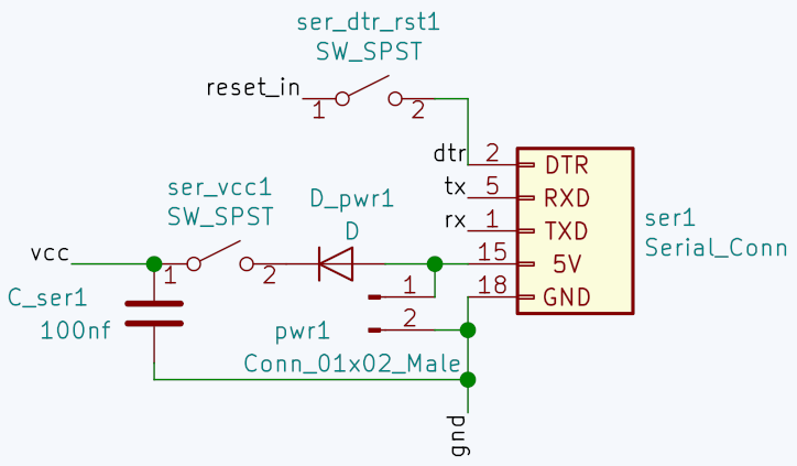
Reset logic
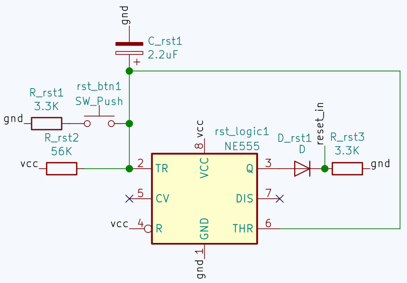
Resets can be triggered in two ways: A reset button is connected to an
NE555 in a monostable configuration. Alternatively, a reset can be
triggered by setting DTR of the serial interface to high. The latter
is used to automatically trigger a reset before program
upload. tools/boot.py uses this to trigger a reset and get Eris 2010
ready for program upload. The disadvantage of wiring DTR to rest is
that Eris 2010 only operates when a terminal is connected; when no
terminal is connected, it stays in reset mode. Therefore a hardware
switch allows to disconnect DTR from the reset line, allowing Eris
2010 to run even if no terminal is connected. In this configuration,
resets for program upload have to be triggered manually. See also
section Booting.
Another way to run Eris 2010 even if no terminal program is running on
your main computer is to configure your computer’s serial interface
to keep DTR low at all times (Linux: stty -F <serial interface> -hup).
Note that the reset line of the 65C02 is active on low. We use the AFT16V8B - which mainly provides the bus logic - as an inverter.
Booting
The “standard” ROM is roms/os/os.bin. This ROM includes the standard
library (for serial communication, accessing SD card, RNG, …). It
provides three methods to load a program:
Via serial line
After a reset, the ROM listens for a serial data transmission at 19200 BPS 8N1. If byte $ff is sent, the download sequence is initiated. The next byte is the number of half-blocks of 256 bit to be loaded. (Block size is 512 bit, because this is the block size of SD cards.) The number of half-blocks is followed by the data. Data is stored at $0200. Once the upload is completed, the upload program returns a two-byte checksum. The first byte is the sum of all bytes transmitted mod 256. The second byte is the xor of all bytes transmitted. The upload program than starts executing the loaded program at $0200.
On the PC, use tools/boot.py for upload.
From SD Card
The boot ROM includes sw/load_from_card/load_from_card.asm, the
program to load programs from SD card. This program is executed when
no program is transmitted via serial line.
SD cards can store up to 10 programs. The file system format is as follows:
Block $00000000 is loaded on initialization. The first two bytes should be $E215. This indicates the file system type. The third byte should be $00. This is the version of the file system. The fourth byte is the number of the program to start automatically, or $ff. In case of $ff, a menu of the programs on the card is presented for the user to choose.
The storage space for the first program starts at $00000001. The storage space for the second program starts at $00010001, for the third program at $00020001, … Thus, each program has a total of $ffff blocks of 512 bytes each available. The first block of each program is the program header. It contains the number of blocks to be loaded, and the app name, a null-terminated string. The actual program code starts with the next block. The program is loaded to address $0200 and executed.
On the PC, use tools/kfs.py to write the SD card.
Interfaces
 Two interface modules are part of the computer system: A serial
interface connected to a USB2Serial adapter provides character I/O and
program upload facilities. An SD card reader provides access to SD
cards with a rudimentary file system. The default operating system
allows to read and execute programs stored on an SD card.
Two interface modules are part of the computer system: A serial
interface connected to a USB2Serial adapter provides character I/O and
program upload facilities. An SD card reader provides access to SD
cards with a rudimentary file system. The default operating system
allows to read and execute programs stored on an SD card.
In addition, a user port on the PCB provides access to all GPIO lines not occupied by the SD card communication interface, and an expansion port provides access to the buses and other internal lines. The expansion port carries two select lines for additional peripheral devices. See section Memory Map above.
Interrupts
The I/O interfaces are wired to IRQ. NMI can be triggered by pushing a
physical button. User programs can write their own ISRs for IRQs. The
ISR for NMIs is set in the ROM. The default ISR dumps the
RAM. Alternatively NMIs may jump into Wozmon. For this, set flag
WOZMON_ON_NMI in roms/os/os.asm. Beware that compiling Wozmon into
the kernel does not conform to the GNU GPL v3 license, because Wozmon
is not offically free software. However I, Gerd Beuster, the author of
the kernel, grant you the right to compile Wozmon into it.
Toolchain
Hardware
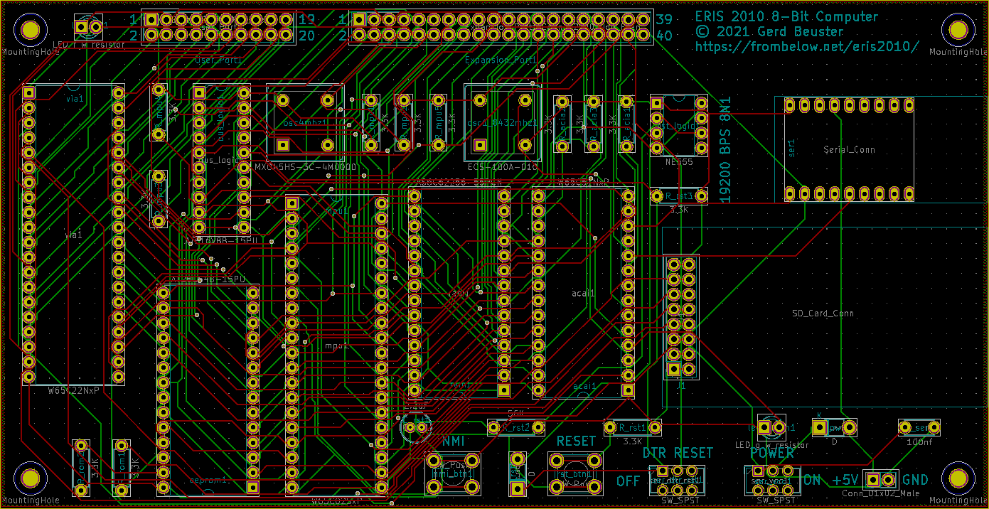 You can find all files related to the hardware design in
hw/pcb/eris2010. The design uses some additional library
symbols. These
additional symbols are copyright (c) 2018, Nicholas Parks Young and
licensed under the GNU LGPL v2.1. The hardware schematics and PCB
layout were designed in KiCad. FreeRouting (part of LayoutEditor) has
been used for routing.
An ATF16V8B-15PU EEPLD is used for the bus logic. It is programmed in GALasm.
Both the EEPROM and the EEPLD can be burned with minipro.
Assembler
All core parts of Eris 2010 have written in assembler. They can be translated with 64tass. The Makefiles generate binary code both for Eris 2010 and Symon. Symon, a 6502 emulator written in Java, has been used for debugging.
Standard Library
A standard library is part of the boot ROM located at roms/os/. In
order to use it, import roms/os/os.inc into your program.
The standard library includes a data stack with subroutines and macros
for local variables and parameter passing. See roms/os/os.asm for
documentation and sw/stack_test/stack_test.asm for examples.
The following functionality is provided:
-
Serial communication interface
All serial communication is conducted at 19200BPS with 8N1. Various input and output functions are provided, including a function that initializes the RNG (see LFSR) by counting ticks when waiting for user input. -
ANSI Terminal
On top of the serial communication interface, the core ANSI escape sequences are supported. -
LFSR
A 16 bit LFSR with maximum period length is provided as PRNG. -
SPI
SPI messages can be send via the VIA. -
SD Card
SD cards can accessed in SPI mode. All addresses are 32 bit, referring to 512 bit blocks on the card. Note that this implementation does not work with all cards. See section bugs below. -
Data Stack
A data stack in software for local variables and parameter passing. In difference to most stacks, the stack grows from bottom to top. The recommended memory layout is program code, followed by heap (if applicable), followed by stack. You have to manually create and delete stack frames with calls to create_stack_frame and delete_stack_frame. Pull and push operations do not push actual data on the stack, but just move the stack pointer. Local variables on the stack are represented by integers and accessed bylda_LOCAL \<number\>,sta_LOCAL \<number\>, and similar macros. Parameters passed bysta_PARAM \<number\>can be accessed by the callee bylda_LOCAL \<number\>. MacroCALLmay be used to call a subroutine with parameters. Refer tosw/stack_test/stack_test.binandsw/load_from_card/load_from_card.asmfor examples.
C
You can program Eris 2010 in C using the CC65 C compiler, available at
https://cc65.github.io/. Suitable configuration and Makefiles, as
well as implementations of the conio and dio libraries, are
located in directory sw/c/cc65_eris. You have to run make once in
this directory in order to generate eris2010.lib. After that, you
can compile the programs in the other subdirectories. The programs
here are simple test programs. Check out contrib/c/ for ports of
(more or less) useful programs.
The conio Library
The conio library for console input/output has been ported to use the serial connection. Since the serial connection is the main I/O connection of Eris 2010, conio and not the serial library is used to access it. Some functions of conio have not been ported because the functionality is not available via a serial line with ANSI encoding:
- bgcolor
- bordercolor
- cpeekc
- cpeekcolor
- cpeekrevers
- cpeeks
The dio Library
The dio library provides low level file system access. dio uses 16 bit sector numbers. Since SD cards use 32 bit sector numbers, we use a hack to be able to access all sectors of the SD card while maintaining compatibility to the dio library: The upper 16 bits of the sector number are encoded as the device handle.
In order to access the SD card, you have to call dio_open
once. Neither the device number you pass into this function nor the
handle returned matter. dio_write and dio_read treat handle as
an unsigned int indicating the upper 16 bits of the sector
number. (dio_write_verify is not implemented.)
Due to our file system structure, this handle is identical to the
application number of the application whose data you are
accessing. The application number is a (the) parameter of main. Use
it to make sure that your program only writes to its own storage space.
Forth
Tali Forth 2 (https://github.com/scotws/TaliForth2) has been ported
to Eris 2010. It resides in directory contrib/forth. Note that Tali
Forth 2 is included as a submodule. Either checkout the Eris 2010
repository with option --recurse-submodules or run git submodule init && git submodule update in the Eris 2010 directory. If you want
to use Tali Forth 2 for any other purpose than running it on Eris
2010, I recommend to use the version from the original repository, not
the one adapted to Eris 2010 used here.
Due to memory constraints, ed has been removed. Even after removing
ed, only approximately 7 KB are free.
Following the SD card structure of Eris 2010, the two upper bytes of the block number are fixed to $00 (MSB) and the application number (second MSB). Since SD card blocks are 512B, but Forth blocks are 1024B, a total of $7fff blocks are available from within the Forth system. These blocks represent the SD card memory available to the Forth application, i.e. the Forth application itself resides in the blocks 0 to 31. If you write to any of these blocks, you overwrite the Forth system! Blocks above 31 are free to use.
Tools
kfs.py
Program for formatting, listing, and writing SD card in a format readable by Eris 2010.
boot.py
Script to upload programs via serial line.
reset.py
Triggers a reset by toggling DTR.
Case
The main purpose of the case is to expose the mainboard. :-)
Therefore it just consists of a top and bottom acrylic plates,
separated by spacer bolts. Laser cutter cutout files are located in
directory case/
Bugs
The communication protocol for SD cards is rather complex. The implementation for Eris 2010 worked with 5 out of 6 cards tested. If it does not work with your card, try a different card (or fix the protocol implementation). :-)
ChangeLog
- v1.2
Tali Forth 2 and Snake added. - v1.1
Support for C programming language. - v1.0
First public version.
Copyright and License
The software in directory contrib/ comes from third parties. Check the
subdirectories of contrib/ for author, copyright, and licensing
information.
Everything else:
Copyright © 2021 Gerd Beuster gerd@frombelow.net
This project is free soft- and hardware: you can redistribute it and/or modify it under the terms of the GNU General Public License as published by the Free Software Foundation, either version 3 of the License, or (at your option) any later version.
This project is distributed in the hope that it will be useful, but WITHOUT ANY WARRANTY; without even the implied warranty of MERCHANTABILITY or FITNESS FOR A PARTICULAR PURPOSE. See the GNU General Public License for more details.
You should have received a copy of the GNU General Public License along with this project. If not, see http://www.gnu.org/licenses/.